INTRODUCTION
The ODEx (Onboard Data Exchange) protocol is a set of specifications for the exchange of real time vehicle data, including:
─ data concerning the physical vehicle (obtained from the vehicle CAN buses and vehicle signals and sensors)
─ data related to the PT services run by the vehicle and
─ data related to the ITS-PT equipment installed onboard.
ODEx uses IP communication between ITS-PT components connected to a common onboard IP network (onboard ITS LAN).
This document describes onboard IP Network requirements to support ODEx communication. It covers the physical layer, IP addressing, name registration and resolution, communications protocols and network security.
ODEx Documents
|
Document |
Contents |
|
ODEx-1. Concepts and Functional Architecture |
|
|
ODEx-2. Network Requirements (This document) |
|
|
ODEx-3. Inventory and Updates Interfaces |
|
|
ODEx-4. Operational Interfaces |
|
|
ODEx-5. Usage and Examples |
|
NETWORK OVERVIEW
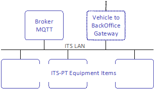
Each vehicle shall have a private IP network (onboard ITS network) to interconnect ITS-PT Equipment Items.
This should be the primary means by which ITS-PT components exchange data within the vehicle level, and by which these components share common resources.
The onboard ITS network must have a single MQTT broker that will be used by ITS-PT components to exchange operational data.
It will normally also have a vehicle to BackOffice communication gateway (vehicle gateway).
ITS-PT Equipment Items on the network may be connected physically as described in the next section or virtually over IP media.
PHYSICAL LAYER FOR IP COMMUNICATION
ODEx IP communication physical layer will be according to CEN/TS 13149-8:2020 Physical layer for IP communication specifications, which include the following sections on which some observations are made that must be considered in ODEx:
- 5.1 General Remarks
- 5.2 Network Structure
- 5.3 Cabling
- 5.4 Connectors
- 5.5 Switches
- 5.6 Power over Ethernet
- 5.7 Shielding and Grounding
─ Both connector alternatives are allowed in ODEx:
─ 4 pin D-coded M12
─ RJ45 (with cable fixed close to the connector to minimize stress on the interconnection)
─ In addition, ODEx recommends a managed switch in the following cases:
─ Need to communicate two different Ethernet branches in legacy systems.
─ To connect Equipment Items which need to be located within the bus (e.g. validators, passenger counting sensors, cameras) so that each physical port of the switch is assigned to a different bus area and the managed switch can inform about the IP connected to each physical port.
─ Recommended for cameras and Passenger counting sensors
GATEWAYS TO OTHER NETWORKS
Besides the onboard ITS network, a vehicle may have several other communication networks (which may or may not be IP-based), such as CAN (Controller Area Network) buses, serial buses like RS485 or independent IP networks where some ITS-PT Equipment Items may be connected (e.g. ticketing systems). Such networks ("external networks") may be connected to the onboard ITS network. Such connections, where they exist, shall be via gateways complying with ODEx specifications to exchange data among components in different networks.

IP ADDRESSING
General considerations
Each Equipment Item connected to the onboard ITS network must have a valid IP address in order to communicate with other ITS-PT components in the network.
ODEx prioritises the use of DHCP for automatic IP address assignment. If DHCP is not available, Equipment Items may self-assign an IP address using ZeroConf mechanisms, either IPv4 Link-Local (RFC 3927) or IPv6 Link-Local (RFC 4862).
All Equipment Items must support assignment via DHCP as the preferred option. In case of failure, they may use self-assignment. Only in exceptional scenarios may manual configuration be used, following a defined procedure that avoids address conflicts.
Addressing space
IPv4 addressing space
IPv4 address assignment must respect the private-use blocks defined in RFC 1918.
In private IP networks, RFC 1918 defines the following address blocks:
|
Name |
RFC1918 |
IP Address Range |
Number of Addresses |
Classful Description |
Largest CIDR Block (Subnet Mask) |
Host ID Size |
|
24-bit block |
Yes |
10.0.0.0 – 10.255.255.255 |
16,777,216 |
Single Class A |
10.0.0.0/8 (255.0.0.0) |
24 bits |
|
20-bit block |
Yes |
172.16.0.0 – 172.31.255.255 |
1,048,576 |
16 consecutive Class B networks |
172.16.0.0/12 (255.240.0.0) |
20 bits |
|
16-bit block |
Yes |
192.168.0.0 – 192.168.255.255 |
65,536 |
256 consecutive Class C networks |
192.168.0.0/16 (255.255.0.0) |
16 bits |
|
Single subnet |
No |
192.168.0.0 – 192.168.0.255 |
256 |
Single Class C network |
192.168.0.0/24 (255.255.255.0) |
8 bits |
Table 2.- Address Blocks in Private IP Networks (RFC 1918)
Where the vehicle will not require more than 256 addresses, a single class C subnet will typically be sufficient and should be used wherever practical.
- Subnet used: 192.168.0.0/24 (mask: 255.255.255.0)
- Address range: 192.168.0.0 ~ 192.168.0.255
- Maximum of 254 usable addresses (.0 is the network address and .255 the broadcast address).
IPv6 addressing space
For networks operating in IPv6, address assignment must meet the requirements of RFC 4291, which defines unicast, multicast and anycast addressing schemes.
ODEx establishes the following IPv6 addressing scheme:
- Private IPv6 prefix (for ODEx): range fdxx::/48, in accordance with RFC 4193.
- Link-Local addresses: range fe80::/64, in accordance with RFC 4862.
Manual assignment
Although ODEx prioritises automatic assignment, manual IP address assignment may be used in exceptional cases. This assignment may be hard-coded in the Equipment Item or configured remotely via the network.
Assignment management must be performed carefully to avoid duplicates, and maintenance support must ensure that the address is not inadvertently changed. If the IP address is hard-coded, it will be necessary at each exchange to ensure it is not duplicated. Using a reference to the installation position would reduce possible errors when using this manual configuration.
Automatic assignment
Assignment via DHCP
The Dynamic Host Configuration Protocol (DHCP) is a way of assigning IP addresses. Its use involves identifying a pool of addresses dedicated to being assigned to modules that can send DHCP requests to a DHCP server. This server is responsible for assigning and managing unique addresses for each module.
The address type must comply with the classes defined by IPv4, as well as IPv6 requirements, depending on the number of addresses managed by the server. As the address map can change dynamically, this must be considered when implementing in an environment with DHCP assignment.
In ODEx, the DHCP server must assign addresses within a single fixed class-C IPv4 subnet (for example, 192.168.0.0/24, assigning addresses between 192.168.0.1 and 192.168.0.252).
- Address 192.168.0.253 must be reserved for the MQTT broker.
- Address 192.168.0.254 must be reserved for the default vehicle to BackOffice gateway.
If needed, other addresses may be reserved for other critical components such as switches or bridges.
Any module that provides a DHCP server must allow the service to be disabled.
Self-assignment
When no DHCP server is detected, Equipment Items may self-assign addresses using standard self-assignment mechanisms:
- For IPv4, RFC 3927 defines the dynamic assignment of IP addresses in the range 169.254.0.0/16 (“IPv4 Link-Local” assignment, IPv4LL).
- For IPv6, RFC 4862 defines the self-assignment of link-local addresses with the prefix fe80::/64.
Mixed assignment
ODEx allows the coexistence of different IP assignment mechanisms, provided the previous ranges and assignment rules are respected. The private range of the onboard ITSnetwork will be divided into two distinguishable ranges using the following combinations:
- The first range dedicated to DHCP assignment and the second range to manual assignment.
Example 1: DHCP + Manual
- The first range dedicated to self-assignment and the second range to manual assignment.
─ DHCP: 192.168.0.1 – 192.168.0.200
─ Manual: 192.168.0.201 – 192.168.0.253
Example 2: Self-assignment + Manual
─ Self-assignment: 169.254.0.1 – 169.254.0.200
─ Manual: 169.254.0.201 – 169.254.0.253
NAME REGISTRATION AND RESOLUTION
Equipment Items must either know or be able to discover the IP address and port of:
- the vehicle gateway.
- the MQTT broker, and
This can be achieved by:
- using fixed (preconfigured) addresses, or
- using Multicast DNS (mDNS) for dynamic discovery.
Fixed Addresses
If fixed addresses are used, the following assignments apply:
- The MQTT broker must be assigned IP address and port: 192.168.0.253:1883
- The vehicle to BackOffice gateway must be assigned IP address: 192.168.0.254
mDNS Discovery
If mDNS is used to discover the MQTT broker and/or the vehicle gateway, they must support mDNS and respond to queries made to the .local domain. The following mDNS names shall be used:
- Default vehicle-to-BackOffice gateway: vehicle_gateway.local
- MQTT broker: vehicle_mqtt_broker.local
Alternatively, the IP address of the vehicle gateway may be found on the MQTT topic:
- odex/ver1.0/general_info/
In this topic additional information about the MQTT broker may be published.
COMMUNICATIONS PROTOCOLS
ODEx uses the following protocols for different functions:
- MQTT (v5.0 / 3.1.1)
─ It is the main ODEx protocol, used for:
─ inventory declaration and discovery of Equipment Items and Providers,
─ providing and consuming status information of Equipment Items and applications,
─ providing and consuming information about software and configuration/data updates
─ providing and consuming operational data
Communication is based on an asynchronous model structured in hierarchical topics, transmitted over TCP/IP (default port 1883, or 8883 if TLS is used).
- mDNS
- SNTP/NTP
- Secure Shell (SSH)
─ The MQTT broker must support both MQTT v5.0 and MQTT v3.1.1 protocols, allowing clients to connect using either version.
─ MQTT clients may be of any of these versions.
─ On powerup, MQTT clients that power up before the broker should continuously attempt to connect until the broker becomes available.
─ Although most ODEx data is published with the retain flag and thus stored by the broker, ITS-PT components will republish all relevant information upon reconnection as a precaution, for instance in case the broker has been reset, or data was lost.
─ Used for the automatic discovery of the onboard MQTT Broker IP and port and the IP of the vehicle gateway.
─ Used for time synchronization with a time source accessible within the onboard ITS network.
─ Alternatively, MQTT may be used if 1s precision is enough.
─ May be used exclusively for technical diagnostics or configuration tasks, always by authorised personnel.
─ Its use must be restricted and properly protected.
ODEx specifications do not prescribe how each ITS-PT component communicates with the BackOffice; each project can have its own vehicle-to-BackOffice communications solution, such us bridging the local vehicle broker with a BackOffice broker and mapping remote topics, allowing each device to use its own protocol or using a gateway device to manage the vehicle-to-BackOffice communications.
MQTT Broker configuration
|
Parameter |
Description |
Value |
Notes |
|
MQTT Version |
MQTT versión of broker |
Always MQTT 5.0 |
MQTT clients may be 5.0 or 3.1.1 |
|
Broker name |
Broker name for mDNS |
vehicle_mqtt_broker.local |
|
|
Port |
Broker Connection port |
1883 for non TLS connections 8883 for TLS connections |
Default ports |
|
Client ID |
Unique identifier supplied by the client (not by the broker). Required to resume a persistent session. |
Recommended: fixed UUIDv4 (RFC 9562) |
Subscriptions (and any QoS 1/2 queues) survive reconnects only if the client reconnects with the same Client ID and the session is persistent. |
|
Session persistence (Clean Session/Clean Start) |
Determines whether the broker retains subscriptions and pending messages after a disconnect. Set by the client (in CONNECT). |
MQTT 3.1.1 Client: CleanSession = 0 Clean Start = 0 and Session Expiry Interval > 0 |
Combine with a fixed Client ID. On each CONNECT the broker returns the Session Present flag in the CONNACK to indicate whether the session and subscriptions remain. |
|
User/Password |
Client user/password to connect to broker |
Required |
No anonymous connections should be allowed unless their access to topics is limited by ACLs. |
|
MQTT connection KeepAlive |
Maximum period of time the connection with a client will be kept active without client-broker communication. |
Any (e.g. 60s) |
The keepalive interval should be selected to ensure that faulty or disconnected clients are detected as quickly as possible, without unnecessarily increasing traffic on the MQTT network. |
|
Last Will (LWT) |
Message that will be published by the broker if a client is disconnected. |
Not defined in ODEx but may be useful to monitor MQTT Client connections if needed and used in a project-specific defined additional topic (e.g. <<root>>/wills). Together with the optional field usageHints in the equipment items and providers /info topic. |
Each client can only specify a single LWT message and topic; thus, it is not suited to monitor providers (that is what the ODEx defined heartbeat topics are intended for). |
|
TLS |
Allows encryption of client passwords when they connect to the broker. |
Recommended mutual TLS authentication using a private created CA in a trusted Equipment Item. |
Without TLS, clients will send their password to the broker without encryption. |
Table 3.- MQTT Broker Configuration
NETWORK SECURITY
The architecture of on-vehicle systems shall be secure against both endogenous (internally-generated) and exogenous (externally-generated) threats.
Endogenous threats are limited due to the environment is physically constrained (inside a bus) but still could
arise from malicious or badly engineered modules being connected to the network.
- Confidentiality compromise may arise if one module allows external access to a second module.
- Availability compromise may arise if one module sends messages which swamp the network.
Exogenous threats include deliberate compromise from hacking, viruses and denial of service attacks, which come through the general Internet. They also include network overload arising from other connected systems such as gateways to other networks or from "tunneled" services such as advertising or services to passenger modules.
Individual components should be designed to protect themselves against threats to integrity and confidentiality, as if they were connected to an unprotected network.
Security functions are not intrinsic to ODEx and must be required as needed in each project. It is recommended that security measures be proportionate to the actual level of risk, in order to avoid hindering implementation or unnecessarily limiting the availability of existing ITS products on the market. This recommendation takes into account the fact that endogenous risks within the onboard environment are low, and that even for more sensitive information exchanged between vehicle electronic systems, the current level of security protection is generally minimal. The following measures are recommended:
- Avoid anonymous connections to the MQTT broker. Clients should be connected using a password.
- TLS could be used in MQTT connections, with a private certificate on a local trusted Equipment Item and application to facilitate its management.
- Use MQTT broker ACL (access control lists) to allow only authorized MQTT clients to access critical topics (e.g. commands)
- Use a secure connection from vehicle to BackOffice (APN, VPN)
- Test Equipment Items and Providers before installation, especially in the case of less known suppliers.
- Isolate the onboard ITS IP network from other networks (e.g. passenger WiFi)
- Detect unauthorized access to buses, particularly when they are parked outside depots or other protected locations.
- Detect and notify the following events:
─ GUID duplication
─ New GUID on the network
─ Incorrect or unusual messages